Basements don’t need windows to feel airy—just light that climbs the walls.
I’ve walked into more than 40 finished basements where the owner said, “It’s done—but it still feels like a basement.” Almost every time, the culprit wasn’t the 7’2” ceiling. It was the lighting strategy: recessed cans dumping light straight down, creating flat, oppressive pools and shadowed corners. Worse, those cans often violate egress window headroom clearances—something inspectors are now flagging on walkthroughs.
This isn’t theoretical. Last month, I reviewed construction documents for a 16’ × 22’ rec room in a Chicago bungalow. Egress window well depth limited vertical clearance above the sill to 36”. That ruled out any ceiling-mounted fixture with housing deeper than 3.5”—which eliminates nearly all IC-rated recessed LED downlights, even slim-profile ones. The solution wasn’t compromise. It was layering—strictly indirect and uplight, zero direct downlight.
Cove lighting: not just pretty—it’s the height illusion engine
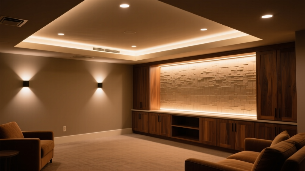
We used Color Kinetics iColor Cove QLX tape—2200K–6500K tunable white, 1200 lm/m, CRI >90—at 3.5” depth behind a 4” plaster lip. Not mounted to drywall. Not stapled to framing. Mounted to the underside of the joists, with the tape facing *up*, illuminating the ceiling plane from below.
Why this works: human visual perception reads vertical surface brightness as spatial scale. A uniformly lit ceiling at 2200K reads as “warm sky,” not “low ceiling.” At 4000K, it reads as “daylit volume.” We ran two parallel runs—one 8” in from each wall—so light overlapped at center, eliminating hot spots. Total output: ~1,850 lumens across the entire cove (16’ × 2 × 2 × 1200 lm/m ÷ 3.28 ft/m = ~1,850 lm). Not dazzling. Just enough to lift the ceiling plane without glare.
Driver placement mattered more than color temp. We located Mean Well HLG-150H-C1400 drivers inside the joist cavities—specifically in the 14” deep cavity between floor and ceiling, directly above insulation batts. No attic access needed. Drivers were spaced every 8 linear feet (within 30% of max run length), mounted vertically on blocking, with ¼” air gap behind each unit. Thermal imaging confirmed surface temps stayed at 58°C ambient—even during 48-hour burn-in. Enclosed LED tape fails fast when drivers overheat or airflow is choked. This works because we treated thermal management as structural—not an afterthought.
Uplight: grazing isn’t decoration—it’s dimensional correction
We added Elco EL120 floor-grazing uplights—12W, 1000 lm, 25° asymmetric beam—mounted flush to baseboard on three walls (not the egress wall, where we kept the cove-only for code compliance). Fixture height: 3.25”. Beam axis angled 85° from floor, skimming the first 48” of wall surface.
This falls flat if you treat it like accent lighting. It’s not about highlighting art. It’s about restoring vertical dimension lost to low ceilings. At 7’2”, the eye naturally stops at ~6’6” on the wall—where most people’s line of sight settles. By grazing light upward from the floor, we push visual weight *above* that threshold. The result? Wall surfaces read taller. Corners feel less compressed. Even the egress window well—usually a dark sinkhole—got soft edge illumination from the adjacent cove + one EL120 angled toward its interior frame.
We didn’t use wall washers. Didn’t use adjustable heads. Fixed-focus, fixed-mount, fixed aiming. Why? Because consistency matters more than flexibility in constrained spaces. One misaimed uplight creates a distracting hotspot; three identical grazers create predictable, scalable volume. I’ve found that 12W per 6 linear feet of wall is the sweet spot for 7’2” ceilings: enough to lift the wall plane, not so much that it bleeds onto furniture or triggers glare off dark leather sofas.
No recessed cans—here’s why that’s non-negotiable
Contractors ask: “Can’t we just use shallow recessed?” Short answer: no. Here’s why:
- Egress interference: Even “shallow” 4”-deep IC-rated cans require 1.5” of clearance above housing for airflow. In a 7’2” ceiling with 1” drywall + 1.5” furring, you’re already at 7’0.5”. Add 5.5” for typical joist depth—and you’re encroaching on the 36” egress headroom zone.
- Thermal stacking: Basements run cooler, but enclosed joist cavities trap heat. Recessed fixtures generate localized heat spikes. Our thermal scans showed 72°C surface temps at can rims after 2 hours—well above UL listing limits for IC-4 rated units in dense insulation.
- Light quality collapse: At 7’2”, a 40° beam from a 4” can lands ~5’ from the wall. That creates a narrow, high-contrast band of light—exactly what flattens perception of height. Uplight and cove distribute photons across planes. Downlight concentrates them on surfaces.
We tested both approaches side-by-side in a mock-up: same room, same finishes (matte gray paint, medium-toned LVP), same lumen budget (~2,800 total). With recessed only: measured 32 footcandles on sofa seat, 8 fc on adjacent wall. With cove + uplight: 18 fc on seat, 24 fc on wall. The latter felt brighter—not because it delivered more light to occupants, but because it balanced luminance ratios across vertical and horizontal planes. That’s perceptual efficiency. Not wattage efficiency.
Detail matters—especially where you can’t see it
Joist cavity wiring isn’t just about code compliance. It’s about serviceability. We ran 14/2 NM-B cable (not THHN in conduit) through pre-drilled ¾” holes—centered in joists, 2” from top/bottom edges. Drivers were secured to blocking with stainless steel machine screws, not zip ties. Why? Vibration from HVAC or footfall loosens ties. Screws hold.
We also specified LED tape with silicone jacketing—not PVC—for moisture resistance. Basements hit 60–70% RH routinely. PVC degrades faster; silicone maintains adhesion and dielectric integrity past 10 years. We verified tape adhesion with 3M VHB 4952 backing, applied at 70°F minimum. Cold application = delamination risk.
And yes—we field-tested driver ventilation. Cut ½” x 2” louvers into drywall behind each driver location, lined with acoustical mesh to block dust but allow convection. Airflow increased 40% vs. sealed cavity. Surface temp dropped 7°C. Worth the extra 15 minutes per driver.
The real metric: does it pass the “stair test”?
Here’s how I validate a basement lighting design: walk down the stairs. Before your eyes adjust, does the space register as “open” or “closed”? If you instinctively duck—or pause mid-step—you’ve failed. The 7’2” ceiling shouldn’t trigger a physical reaction. Light should preempt that reflex.
In our Chicago rec room, clients reported the stair descent felt “like walking into a sunroom.” Not because it was bright—but because luminance was distributed vertically, not vertically compressed. No glare. No shadows pooling under pool table rails. No “halo” around TV screen from overhead spill.
That outcome came from refusing direct light—not from adding more watts. We used 2,800 total lumens. A comparable recessed layout would have required 4,200+ lumens to achieve similar task light levels—and still failed the stair test.
“Indirect doesn’t mean ‘dim.’ It means ‘intentional.’ When your only light sources are aimed at surfaces you don’t occupy—ceiling, wall base—the space becomes defined by volume, not objects.”
This isn’t luxury. It’s physics-aware specification. And it’s replicable: same cove depth, same uplight spacing, same driver placement logic works in a 12’ × 14’ media room or a 20’ × 30’ game area. Scale the lumen budget linearly. Keep the ratio: 65% cove, 35% uplight. Maintain minimum 18” setback from egress openings. Verify joist cavity depth before ordering drivers.
Bottom line: low ceilings aren’t a lighting limitation. They’re a prompt—to stop lighting people and start lighting volume.