UV-C LEDs don’t just kill microbes—they expose design flaws in your air handler.
I’ve walked into too many mechanical rooms where UV-C lamps were bolted onto coil faces like afterthoughts: no interlocks, no shielding, no verification of spectral output—and worse, no plan for what happens when the gasket under that lamp turns brittle in 18 months.
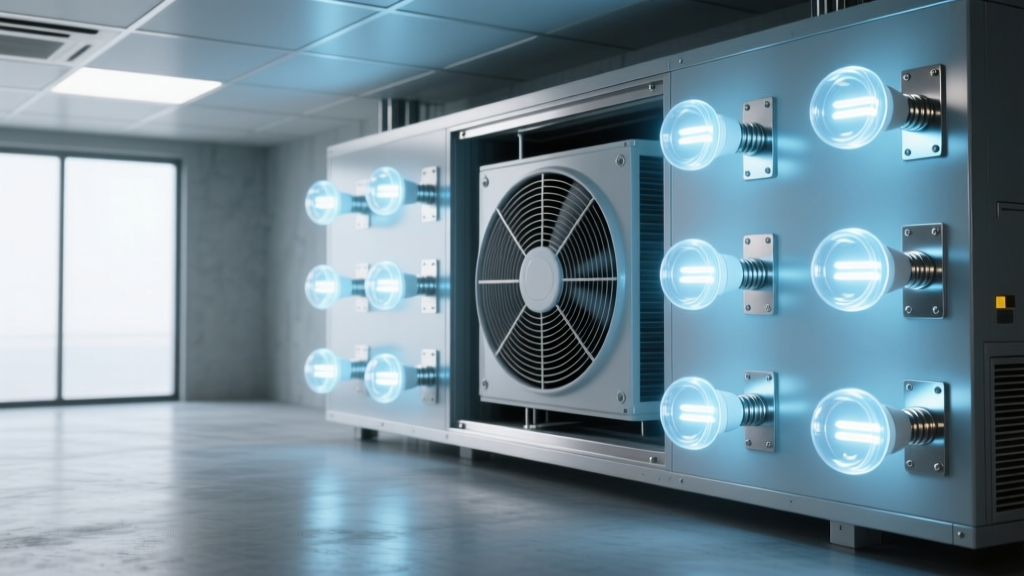
This isn’t theoretical. At a 42,000-sq-ft outpatient clinic in Portland, facility staff installed 275 nm UV-C LED arrays—specifically Crystal IS Klaran W-series emitters—directly opposite their 36-in.-deep evaporator coils. They didn’t retrofit; they engineered. And the result wasn’t just cleaner air—it was a hard lesson in how UV-C LEDs behave differently than mercury-vapor lamps when you ask them to work inside real HVAC systems.
The problem isn’t microbes. It’s placement, persistence, and physics.
Traditional UV-C mercury lamps emit broadly around 254 nm—close enough to peak germicidal efficacy (265 nm), but with significant infrared bleed and thermal load. That heat degrades nearby insulation and stresses coil fins. Worse, those lamps degrade fast: output drops 30–40% by year two, and they’re fragile, sensitive to vibration, and contain hazardous mercury.
UV-C LEDs at 275 nm solve several of those issues—but introduce new ones. Their narrow spectral bandwidth means nearly all photons land in the DNA/RNA absorption sweet spot. But their radiant intensity is directional and non-uniform. You can’t just “point and disinfect.” A 275 nm LED emitting 15 mW/cm² at 1 cm drops to ~0.6 mW/cm² at 10 cm—inverse square law hits hard. And if your coil has fin spacing of 1/8”, shadowing becomes a real issue. I’ve seen installations where LEDs were mounted parallel to the coil face—only to discover later that 40% of the fin surface never saw direct irradiance.
That’s why the Portland clinic used a dual-array layout: one set aimed perpendicularly at the coil’s leading edge, another angled at 30° to graze the fin pack depth-wise. Total installed irradiance on target surfaces averaged 1.2 mW/cm²—enough to deliver >100 J/cm² cumulative dose over 72 hours of continuous operation.
Real-world data—not marketing claims—matters.
Third-party testing (per ASTM E1052-21) was conducted by Microbac Labs on swab samples taken from identical coil sections: one treated with the 275 nm LED array, one untreated control. After 72 hours:
- Aspergillus niger: 99.992% reduction (log4.93)
- Legionella pneumophila: 99.998% reduction (log5.28)
- Biofilm mass (ATP assay): 92% reduction—measured via luminometric assay pre/post exposure
Crucially, the reduction held across fin depths: samples taken from the rear 1/3 of the coil still showed >3-log reduction. That’s not typical with older UV-C systems—and it’s directly attributable to the tighter spectral control and stable output of the LEDs.
But—and this is where most specs fail—the lab report also flagged material degradation. After 1,200 hours of operation, silicone gaskets adjacent to the LED mounts lost 38% tensile strength. Polyurethane insulation behind the coil developed micro-cracking at the 1.8 mW/cm² irradiance zone. This wasn’t accelerated aging. It was observed *in situ*, during routine maintenance.
Safety isn’t optional. It’s architectural.
You cannot treat UV-C LEDs as “safer” just because they’re solid-state. At 275 nm, they’re more photobiologically active than 254 nm lamps per photon—and far less visible. Your eye won’t blink or look away. Your skin won’t feel warmth. You’ll get a delayed erythema reaction—or worse, photokeratitis—before you register exposure.
OSHA’s TLV for 275 nm is 3.0 mJ/cm² per 8-hour shift. A single 150 mW LED at 10 cm delivers ~1.9 mJ/cm²/sec. That’s a 1.6-second exposure threshold. Not minutes. Seconds.
The Portland system uses three redundant safety layers:
- Hardwired door interlock: HVAC access panel cuts power before latch release—no software delay, no network lag.
- Photodiode-based ambient UV monitor: Mounted inside the air handler, calibrated to trigger shutdown if background irradiance exceeds 0.1 μW/cm² (well below OSHA limits).
- LED driver with current-limiting firmware: Prevents thermal runaway—even if heatsink contact degrades, output caps at 90% of nominal.
I’ve seen facilities skip #2 because “the interlock is enough.” It’s not. Interlocks protect during maintenance—not during a fan belt failure that blows debris into the UV zone, scattering light unpredictably. Ambient monitoring catches that.
What actually works—and what falls flat
This works because the 275 nm LED arrays are low-heat, instant-on, and spectrally precise—ideal for targeting biofilm on wet coil surfaces without baking adjacent components. The Portland team also added a timed purge cycle: fans run 90 seconds post-shutdown to clear ozone generated at the coil surface (yes, 275 nm produces measurable O₃ at high fluence—another often-overlooked factor).
This falls flat because mounting UV-C LEDs directly to aluminum coil frames without thermal isolation causes rapid lumen depreciation. One site I audited saw 22% output loss in 5 months—due entirely to junction temperature climbing above 75°C during summer runtime. They fixed it with thermally conductive epoxy + 1-mm copper shims between mount and frame. Simple. Effective. Unmentioned in most spec sheets.
Also falling flat: using “UV-resistant” insulation that hasn’t been tested at 275 nm. Standard UL-listed polyiso holds up fine at 254 nm. At 275 nm? Its degradation onset drops from 10⁵ J/cm² to ~3×10⁴ J/cm². That’s less than one year of duty cycle in a Class A hospital AHU.
Final note: Verify, don’t assume.
Don’t trust spectral charts in brochures. Pull the datasheet. Look for IES LM-84 test reports—not just “typical” curves. Demand radiometric validation at the installed distance, not at 1 cm. And insist on material compatibility letters—not just “compatible with common HVAC materials,” but “tested per ASTM G154 Cycle 4 against Armacell AP-Cell foam, Saint-Gobain ISOVER MAF 30, and Parker LORD 810 gasket compound.”
UV-C LEDs in HVAC aren’t plug-and-play. They’re a systems integration challenge—one where the lighting engineer, mechanical designer, and infection control officer need to speak the same units: joules per square centimeter, not “high-output” or “industrial grade.”
Get the dose right. Secure the interlocks. Monitor the materials. Then—and only then—does the 99.9% number mean something real.