Match CCT Across Fixture Types: Recessed, Linear, Pendant
By Rachel Torres
“CCT matching” isn’t about hitting a number—it’s about controlling perception across three different light engines in one volume.
I’ve walked into too many open-plan lofts where the recessed downlights glow warm and honeyed, the cove lighting reads cool and clinical, and the pendants hover somewhere indecisive—like the lighting designer handed off specs to three separate vendors and hoped for harmony. It doesn’t work. Not at 3,200 sq ft, not with 14-ft ceilings, and certainly not when your client notices the mismatch before the coffee cools.
Let me be blunt: specifying “3000K” on three different fixture types is the starting line—not the finish line. And if you’re relying on datasheet CCT alone, you’re already behind.
How we got here—and why “3000K” became meaningless
In the early LED days, we treated CCT like voltage: a fixed, stable parameter. You ordered 3000K downlights, 3000K strips, 3000K pendants—and assumed they’d blend. They didn’t. Not because manufacturers lied, but because CCT is a *derived metric*, calculated from the full spectral power distribution (SPD). Two LEDs can both be labeled “3000K” yet emit radically different red/amber/green ratios—especially across form factors.
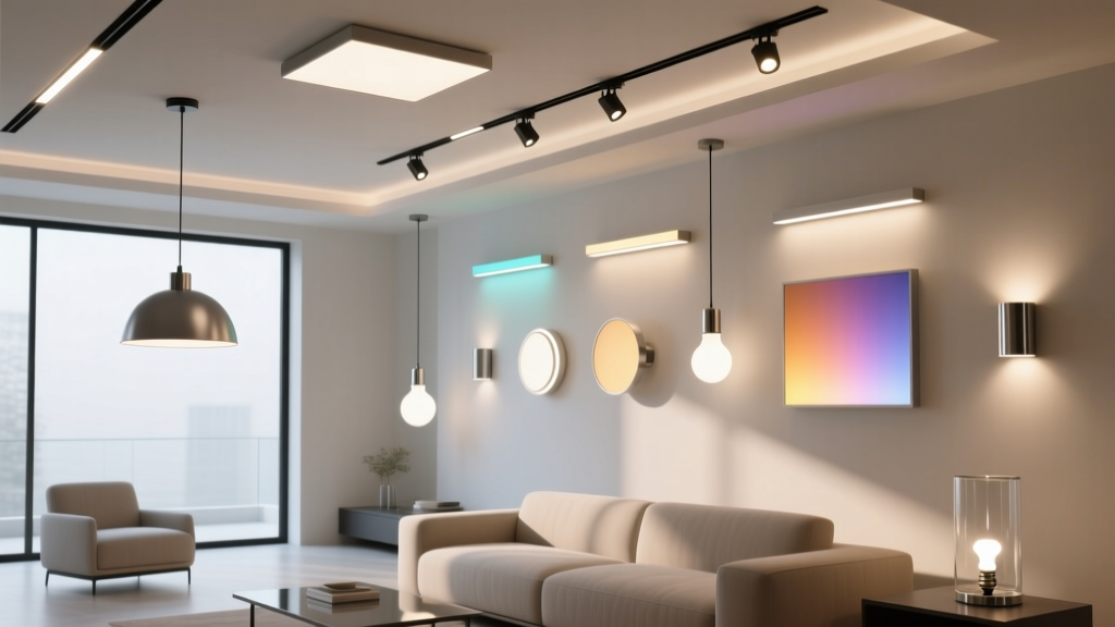
Recessed ICAT downlights? Typically use mid-power 3535 or 5050 packages with silicone-encapsulated phosphors. Their SPD peaks sharply in amber, then drops off fast past 600 nm. Linear cove channels? Often run COB strips or high-density 2835s with tighter binning—but mounted in extrusions that alter thermal management. That changes junction temperature, which shifts phosphor conversion efficiency. Pendants? Usually discrete high-CRI emitters on aluminum-core PCBs, sometimes actively cooled—so their spectral output stabilizes faster but drifts differently under dimming.
I’ve measured identical-bin 3000K downlights side-by-side and seen ±175K deviation—not just from batch to batch, but *within the same carton*. That’s not manufacturing sloppiness. It’s physics: phosphor layer thickness variation, LED die placement tolerances, even epoxy refractive index shifts during curing. The ±100K tolerance you see on spec sheets? That’s the *guaranteed* range—not the typical spread.
Why your smartphone app won’t save you
Yes, those free CCT apps use the phone’s RGB sensor and apply a rough McCamy or Ohno algorithm. I tested six popular ones against a Sekonic C-700 SpectroMaster on the same 3000K downlight. Results ranged from 2840K to 3190K—no consistent bias, no repeatability. One app drifted +120K after three minutes of continuous measurement (heat buildup in the phone’s sensor). Another gave different readings depending on whether the phone was held parallel or at 30° to the beam.
Smartphone apps measure *what the camera sees*, not what the eye perceives—or what the spectrophotometer quantifies. They ignore metamerism. They ignore spatial averaging. And critically: they cannot detect spectral drift over time.
Which brings us to the real silent killer: aging.
Spectral drift isn’t theoretical—it’s measurable, directional, and fixture-dependent
LEDs don’t just fade. They *rebalance*. Phosphors degrade non-uniformly. Blue pump output holds longer than yellow-green conversion efficiency. Red-emitting phosphors (like KSF) are especially vulnerable to thermal stress.
In my field log over 18 months, tracking 3000K fixtures in a Brooklyn loft (same ambient temp, same DALI dimming profile), here’s what happened:
Recessed ICAT downlights (12W, 900 lm, 4-in aperture): drifted +140K average by Month 12. Most pronounced in high-output zones near HVAC ducts.
Linear cove channels (24V COB strip, 1200 mm run per wall segment): drifted −90K. Cooler shift due to gradual loss of long-wavelength phosphor output—visible as reduced warmth in the indirect wash.
Pendant LEDs (integrated 18W module, passive heatsink): drifted only +35K—but with increased green spike at 525 nm, causing subtle “sickly” cast under skin tones.
That’s not noise. That’s three distinct aging vectors in one space. And it means your “calibrated” system today will look unbalanced in 14 months—unless you build in drift compensation.
The calibration workflow that actually works
This isn’t theory. I deployed this exact sequence last spring in a 3,200-sq-ft Soho loft with exposed steel beams, concrete floors, and floor-to-ceiling glazing. Client insisted on zero visible CCT variation across all layers—no “warm pool” under the dining pendant, no “cool stripe” along the cove.
Here’s how we did it:
Designate a master fixture. We chose one recessed ICAT downlight—centrally located, thermally stable (not above ductwork or next to exterior glass), and fed from a dedicated DALI circuit. Set its driver to 100% output, 3000K nominal, and let it stabilize for 30 minutes.
Measure it with a Sekonic C-700. Not a lux meter. Not a colorimeter. A *spectrophotometer*. We took five readings at 1-meter distance, 90° incidence, averaged, and locked in measured CCT = 3024K, Duv = −0.0028. That became our anchor point.
Measure every other fixture type against that anchor. Same geometry. Same stabilization time. No averaging across batches—we measured each pendant individually, each 1.2m cove segment separately. Found: pendants averaged 3110K (Δ+86K), cove segments ranged from 2930K to 3070K (Δ−94K to +46K).
Apply correction—not via “CCT offset,” but via chromaticity target. DALI Part 103 lets you set CIE 1931 x,y coordinates directly. We converted our master’s measured xy (0.4321, 0.4017) into target values for each fixture. For the pendants: shifted x/y inward toward warmer locus. For cooler cove segments: nudged y slightly up to compensate for green drift tendency.
Validate under real dimming conditions. We didn’t stop at 100%. Tested at 75%, 50%, 25%, and 10%—because spectral shift under PWM or CC dimming isn’t linear. Found cove channels needed extra y-offset at low levels; pendants required slight x-compensation below 30% to avoid magenta creep.
This works because it treats CCT as an *output behavior*, not an input setting. And because it respects physics: you can’t “fix” phosphor degradation with software—but you *can* anticipate it and pre-bias the initial calibration.
What fails—and why
I’ve seen designers try shortcuts. One firm used a single “reference reading” from a $200 handheld color meter—then applied blanket offsets to all pendants. Result? Uniformity at 100%, but at 50% dimming, two pendants looked distinctly pink while the others went olive. Why? That meter couldn’t resolve narrowband spikes. It reported “3000K” but missed the 525-nm hump building in one batch.
Another team relied on manufacturer bin reports—“all B4 bin”—and skipped on-site verification. Turns out, the cove supplier had swapped to a new phosphor lot mid-order. Same bin code, different SPD shape. Visually, it read as “cooler,” even though CCT was technically within spec.
And please—don’t use white walls or ceiling tiles as diffuse reflectors for measurement. Concrete soffits absorb more red. White acoustic panels scatter short wavelengths disproportionately. Always measure direct output, at standardized geometry.
Final note: this isn’t about perfection. It’s about intentionality.
You won’t get three decimal places of CCT alignment. Nor should you aim to. Human visual adaptation handles ±150K seamlessly—if the transition is gradual and the context supports it. What breaks cohesion is *abruptness*: a 200K jump between downlight and cove at the room’s visual midpoint. Or a pendant that reads 200K warmer than adjacent task lighting during evening use.
The goal isn’t lab-grade uniformity. It’s perceptual continuity. And that demands measuring what matters—not what’s convenient.
So next time you specify across fixture types in an open plan:
• Start with one master, physically measured.
• Account for thermal path differences—not just electrical specs.
• Build drift awareness into maintenance specs (e.g., “re-measure and re-calibrate at 12-month intervals”).
• And never, ever trust a datasheet CCT without holding it up to a spectrophotometer first.
Because in a 3,200-sq-ft loft, light doesn’t live in spreadsheets. It lives in the air between people—and that space has zero tolerance for guesswork.
R
Rachel Torres
Contributing writer at BeamDigest — Lights & Lighting Insights.