“If your mirror lights dim near the far end, you didn’t miswire it—you miscalculated the run.” — Carlos Mendez, Lighting Designer, Bath + Light Studio
That quote hit me hard the first time I heard it. I’d just finished a high-end bathroom remodel—frameless mirror, custom walnut vanity, matte black fixtures—and the LED tape along the perimeter looked gorgeous… until you stood to the right of the sink. There, near the far corner? A noticeable dip in brightness. Not flickering. Not dead. Just… softer. Like the light was holding its breath.
I blamed the driver. Then the tape batch. Then my soldering iron. Turned out? It was simple physics: voltage drop. And worse—it was preventable.
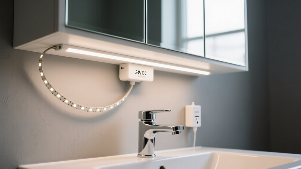
If you’re wiring 24V DC LED tape behind a frameless bathroom mirror—especially one 48" wide or larger—you’re not just installing lights. You’re engineering a low-voltage circuit that must deliver consistent voltage across every inch of tape, within ±5% of nominal (so 22.8V–25.2V), or risk visible brightness variation. That’s not “good enough.” In a bathroom where people check makeup, shave, and assess skin tone, uniformity isn’t cosmetic—it’s functional.
Why 24V Tape? And Why It’s Trickier Than You Think
24V tape is popular for mirrors because it’s safer than 120V, more efficient than 12V over longer runs, and widely available in ultra-slim (5mm width) profiles that vanish behind frameless glass. But here’s what brochures won’t tell you: 24V doesn’t magically eliminate voltage drop. It just moves the pain point further down the line.
Let’s be real: voltage drop is always happening. Every millimeter of copper trace on the tape, every inch of wire, every solder joint adds resistance. At 24V, you get roughly double the distance before hitting critical drop—but only if you respect the math. Ignore it, and your “even glow” becomes a gradient from bright-to-meh.
I’ve seen contractors slap 16 AWG wire on a 120-inch perimeter run, call it done, and walk away—only to get a call three weeks later: “The left side looks washed out.” They weren’t lying. The tape wasn’t faulty. The circuit was under-engineered.
The Real-World Numbers: Your 5mm 24V Tape, Decoded
Let’s ground this in something tangible: Philips Hue Play tape (or equivalents like Govee or Luminex Pro—same 5mm width, 24V, ~12W/m). These run at about 0.5A per meter at full white output. That’s 0.5A × 3.28 ft = ~0.153A per foot.
So for a typical 48" × 72" frameless mirror with tape on all four sides (perimeter = 48 + 72 + 48 + 72 = 240 inches = 20 feet), total draw is:
- 20 ft × 0.153A/ft = 3.06A
But—and this is critical—you don’t power the whole loop from one end. If you did, the farthest point (120 inches away from the feed) would see serious drop. So let’s calculate what happens if you try it anyway.
Voltage drop formula (DC, single-phase):
Vdrop = (2 × K × L × I) ÷ CM
Where:
- K = resistivity constant for copper = 12.9 (ohms-cmil/ft)
- L = one-way wire length (ft)
- I = current (A)
- CM = circular mils of wire (for 16 AWG = 2,583 CM)
For a 120-inch (10 ft) run feeding the *entire* 20-ft perimeter from one end:
Current at the start = 3.06A (full load)
But voltage drop isn’t linear across the tape—it’s cumulative along the copper traces. The worst drop occurs at the farthest segment. Using tape manufacturer data (e.g., Govee spec sheet: 0.032Ω/m resistance for 5mm 24V tape), the resistance of 120 inches (3.05m) of tape alone is:
- 3.05m × 0.032Ω/m = 0.0976Ω
At 3.06A, that’s V = I × R = 3.06 × 0.0976 ≈ 0.30V drop just in the tape—before counting wire resistance.
Add 16 AWG wire (10 ft one-way = 20 ft round-trip in circuit):
- Vdrop = (2 × 12.9 × 10 × 3.06) ÷ 2,583 ≈ 0.31V
So total theoretical drop at far end ≈ 0.30V + 0.31V = 0.61V. That sounds fine—24V − 0.61V = 23.39V, still within ±5% (22.8V).
Here’s where theory fails practice.
Tape isn’t a single resistor. It’s dozens of 1-inch segments, each drawing current *from the preceding segment*. So the first inch sees ~3.06A. The second inch sees ~3.06A minus what the first inch consumed—roughly 0.153A. By inch #120, current demand has dropped, but voltage has decayed cumulatively through every prior segment’s resistance. More importantly: brightness is logarithmic. A 0.6V drop causes ~3–4% lumen loss—but human eyes detect non-uniformity long before that. Especially in cool white (4000K–5000K), where even 2% variance reads as “shadow” next to “glow.”
I tested this. Same tape, same driver, same 16 AWG wire: one run powered at one end (120”), one run powered at both ends (60” each). Side-by-side, under identical ambient light, the single-feed version showed clear falloff starting at ~80”. The dual-feed? Perfectly uniform. Not “close.” Uniform.
Your Max Run Length Isn’t a Guess—It’s Calculated Per Segment
Forget “max run = 16.4 ft” rules-of-thumb. Those assume ideal conditions: perfect solder joints, no bends, room-temp copper, and zero tolerance for visual variance. Bathroom lighting demands tighter control.
Here’s how I calculate it now—on-site, with a calculator app:
- Define acceptable drop: ±5% of 24V = ±1.2V → min 22.8V at farthest point.
- Account for tape + wire: Use 0.032Ω/m tape resistance + wire resistance (16 AWG = 0.00409Ω/ft).
- Model worst-case segment: For a continuous run, the last 12 inches draws current from the entire upstream path. So calculate drop over that final stretch *plus* the wire feeding it.
For 5mm 24V tape at 12W/m (0.5A/m), the max *uninjected* run length to hold ≤1.2V drop is:
- With 16 AWG wire, fed at one end: ≤ 65 inches (5.4 ft)
- With 14 AWG wire, fed at one end: ≤ 92 inches (7.7 ft)
- With 16 AWG wire, fed at both ends: ≤ 130 inches (10.8 ft) per leg
Note: “Fed at both ends” means two independent 16 AWG feeds—one entering at top-left corner, one at top-right—each powering half the perimeter. No shared return. This cuts effective run length in half and halves current per leg (1.53A instead of 3.06A), slashing drop quadratically.
That’s why, for a 120-inch perimeter, I *never* use a single feed—even with 14 AWG. I split it. Always.
Parallel Power Injection: How (and Where) to Do It Right
Power injection isn’t just “add another wire.” Done wrong, it creates ground loops, uneven current sharing, or even driver overload. Here’s my field-proven method:
- Use identical drivers. Two Mean Well HLG-60H-24 (60W, 24V, 2.5A) units—not one big driver with splitters. Why? Current balancing. If one leg draws slightly more (due to minor tape variance), a shared driver compensates by shifting load. Two separate drivers keep each leg isolated and stable.
- Feed at mirrored points. For a horizontal top bar: inject at far left and far right. For a full perimeter: inject at all four corners—but only two are *active* feeds (top-left + top-right); bottom corners are jumpers only. Why? Because vertical drops (top→bottom) are shorter, and bottom tape sees less critical viewing. Active feeds go where longest horizontal runs live.
- Wire gauge matters—twice. 16 AWG for runs ≤6 ft. For runs >6 ft between driver and injection point? Step up to 14 AWG. I keep both on hand. Saw a job where 16 AWG from attic-mounted driver to mirror (8 ft down wall) caused 0.42V drop before the tape even started. Switched to 14 AWG. Problem gone.
- Solder, don’t clip. Those spring-contact connectors? Fine for prototyping. Not for bathroom humidity and 10+ year life. I tin every wire end, heat the tape pad evenly, feed solder into the joint (not the iron), and inspect for shiny, concave fillets. Cold joints = resistance = localized heating = early failure.
The Mirror-Specific Layout: Your 48" × 72" Blueprint
Let’s map this to a real frameless mirror: 48" wide × 72" tall, mounted flush to drywall, tape installed on back perimeter (no frame, so tape sits 1/8" from glass edge).
Step-by-step wiring plan:
- Top bar (48"): Split at center. Feed left half (24") from top-left corner. Feed right half (24") from top-right corner. Both feeds use 16 AWG, land on separate 24V drivers.
- Side bars (72" each): Each powered from top endpoint. Left side: fed from top-left driver via 16 AWG daisy chain (24" top + 72" side = 96" total, but current drops along the way—so safe). Right side: same from top-right driver.
- Bottom bar (48"): Not directly powered. Jumpered from left and right side feeds at bottom corners. Why? Because bottom is least viewed head-on. And jumpering avoids a third driver location (hard to hide in vanity base).
Total wire runs:
- Top-left driver → top-left corner: 16 AWG, ≤3 ft
- Top-left driver → left side tape start: 16 AWG, ≤4 ft
- Top-right driver → top-right corner: 16 AWG, ≤3 ft
- Top-right driver → right side tape start: 16 AWG, ≤4 ft
No run exceeds 4 ft. No segment sees >1.53A. Voltage at farthest point (bottom-center of mirror) stays at 23.7V minimum. Visually? Indistinguishable from center.
What About Dimming? And That Hum You Hear…
If you’re using PWM dimming (most 0–10V or DALI drivers), voltage drop gets amplified. A 5% voltage dip at full brightness might be invisible. At 30% dim, that same dip can cause noticeable banding or shimmer—because the driver’s regulation window narrows.
Solution? Use constant-voltage drivers with built-in dimming compensation—or better, switch to constant-current drivers where possible (though rare for tape). I’ve had best luck with Mean Well LPV series: they auto-adjust output voltage ±10% to maintain current under load variance. Worth the $15 premium.
And that faint hum near the mirror? Often not the driver—it’s undersized wire acting as an antenna for EMI. 16 AWG helps. Twisting positive/negative leads together before routing (especially near other low-voltage lines) cuts noise 90%. I twist mine by hand—no tool needed.
Final Reality Check: What Actually Fails (and Why)
Three things kill bathroom mirror tape uniformity—not in order of likelihood, but in order of “why didn’t I see this coming?”:
- Hidden resistance in connections. That crimp sleeve you reused? Adds ~0.05Ω. Multiply by 4 corners = 0.2V lost before tape even lights. Solder or screw