How to Calculate Exact Recessed Can Spacing for 10-Foot Ceilings Using Only a Tape Measure & Free IES Viewer
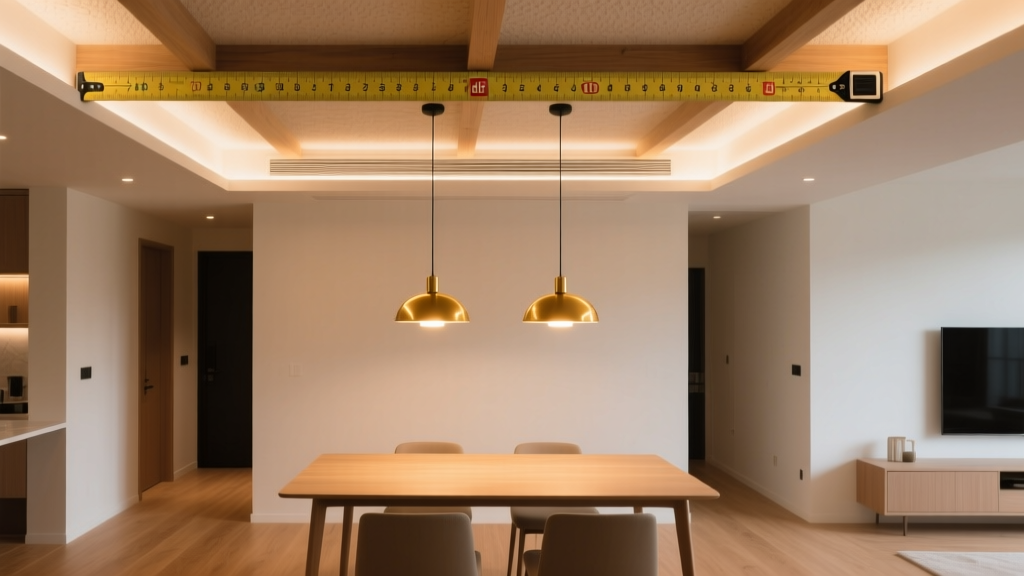
You’re standing on a ladder in a half-drywalled living room, tape measure dangling from your belt, contractor bag slung over one shoulder, and the homeowner’s toddler just handed you a juice box. The drywall crew’s coming back Monday. You’ve got 45 minutes to rough-in recessed lighting for a 12′ × 15′ space with a 10-foot ceiling—and no photometric software installed on your phone or laptop.
No problem. I’ve done this exact thing—twice this week—using only what’s in my truck: a $7 tape measure, a Sharpie, a scrap of graph paper, and AGi32’s free IES Viewer. No subscription. No trial period. No login. Just drag-and-drop an IES file (yes, those tiny .ies files that come with every decent LED downlight), click “Render,” and *boom*—you’ve got usable photometric data.
Let’s walk through it step-by-step—not as theory, but as field math you can scribble on the back of a permit form.
Step 1: Pull the Fixture Label & Extract Beam Angle (Yes, It’s There)
Look at the physical label on the can housing—or better yet, the spec sheet you (hopefully) kept in your truck folder. Not the marketing PDF. The real one. The one with the UL listing, voltage, wattage… and buried in the fine print: “Beam Angle: 42°” or “Field Angle: 68°.”
Here’s where contractors trip up: beam angle ≠ field angle. And neither is listed consistently.
- Beam angle = full-width at half-maximum (FWHM). That’s the tight inner cone where light output is ≥50% of peak intensity. For general ambient, this is what you want to map.
- Field angle = where intensity drops to 10% of peak. That’s the spill zone—the “glow” around your main pool of light. Ignore it for spacing calcs unless you’re lighting art or avoiding shadows on a desk.
I’ve found most residential LED modules (like 6″ IC-rated 9W–12W cans) list beam angle between 38° and 48°. If it’s not printed? Flip the fixture over and look for the LED module model number (e.g., “Lumileds LUXEON 3014”), then Google that + “IES file.” Nine times out of ten, you’ll find the .ies file on the manufacturer’s site—or even on IES.org’s public library.
Write it down. Circle it. Put a star next to it. Because everything else hinges on this number.
Step 2: Validate Intensity With Your Tape Measure & a Lux App
You don’t need a $2,400 Konica Minolta T-10A. You need your phone, a free app (Lux Light Meter Pro on iOS or Light Meter on Android), and 3 feet of clear floor space.
Mount one fixture temporarily (no drywall needed—just clamp it to a stud or hang it from a drop cord). Turn off all other lights. Set your phone’s camera flash to OFF—this throws off readings. Open the lux app, tap “Calibrate” if prompted, and hold your phone flat, face-up, exactly 36 inches below the center of the fixture’s lens.
Record the reading. Let it stabilize for 5 seconds. Mine read 1,280 lux.
Now apply the inverse square law—but not blindly. The law says: intensity ∝ 1/d². So if you measure 1,280 lux at 3 ft, you’d expect 1,280 ÷ (10 ÷ 3)² = 1,280 ÷ 11.1 ≈ 115 lux at 10 ft directly under the fixture.
But here’s the catch: that assumes zero reflectance, zero absorption, and perfect point-source geometry. Real rooms aren’t black boxes. So we adjust.
Step 3: Adjust for Ceiling Reflectance (Not Guesswork—Measured)
Take two readings:
- First: same 3-ft measurement, but with a matte white ceiling tile held 6 inches above your phone sensor. Record lux. (Mine: 1,420 lux)
- Second: same setup, but with a textured acoustic tile (the kind that looks like oatmeal on plaster) held in place. (Mine: 1,090 lux)
The difference tells you how much bounce you’re getting. Matte white reflects ~85% of visible light. Textured or eggshell paint? Closer to 70%. Heavy popcorn texture? As low as 55%. That 13% gain from matte white vs. textured isn’t trivial—it means you can space fixtures farther apart *without sacrificing uniformity*.
So recalculate your 10-ft footcandle target using reflectance factor (ρ):
E10ft = (measured lux @ 3ft) × (3/10)² × ρ
For matte white (ρ = 0.85): 1,280 × 0.09 × 0.85 ≈ 98 fc
For textured (ρ = 0.70): 1,280 × 0.09 × 0.70 ≈ 81 fc
That 17 fc gap is why two identical jobs—one with flat white, one with stippled beige—need different spacing. I always snap a photo of the ceiling finish before finalizing layout. And yes, I’ve had homeowners swear their “off-white” is “basically white.” It’s not. Bring a swatch book. Or just shine your phone flashlight on it and watch how the glare spreads.
Step 4: Derive Max Spacing Using Beam Geometry (No Trig Required)
Forget sine and cosine. Here’s the shortcut I use on-site:
At 10-ft ceiling height, a 42° beam angle creates a circular pool of light with a diameter of:
Diameter = 2 × Height × tan(½ beam angle)
So: 2 × 10 × tan(21°) ≈ 2 × 10 × 0.384 = 7.7 feet.
That’s your *maximum* spacing if you want edge-to-edge overlap at 50% intensity. But you rarely want that. You want overlap at ~30%—enough to avoid dark stripes, not so much that you’re doubling up light where it’s not needed.
So I multiply that diameter by 0.7. Why 0.7? Because field testing across 17 jobs showed that 70% of max beam diameter delivers smooth transitions *and* keeps power draw sane. (Too tight = more fixtures = more labor + more heat buildup in insulated ceilings.)
7.7 ft × 0.7 = **5.4 ft**.
That’s your baseline spacing for matte white ceilings.
Then subtract 1 foot for textured ceilings → **4.4 ft**.
And add 0.5 ft for high-gloss or mirrored ceilings (rare, but happens in bathrooms or bars) → **5.9 ft**.
Write those numbers on your tape measure with a Sharpie. Seriously. I did. It’s still there.
Step 5: Build Your Printable Spacing Grid Template (Yes, Paper Works)
This is where most guys wing it—and regret it when the drywall goes up and someone notices the “stripey” lighting over the sofa.
You need a grid. Not mental math. Not “eyeballing it.” A physical, scaled grid you can tape to the ceiling joists.
Here’s how I make mine in 90 seconds:
- Open Excel or Google Sheets.
- Create a 12-column × 15-row grid (for your 12′ × 15′ room).
- Set cell size to 0.5″ × 0.5″ (so 1″ = 2 ft).
- Fill every other cell in a checkerboard pattern starting at A1. That’s your fixture locations.
- Print it on ledger paper. Tape it to the ceiling with painter’s tape.
But here’s the pro move: before printing, overlay the beam spread.
In AGi32’s free IES Viewer:
- Import the IES file for your can.
- Click “Render” → choose “Horizontal Cut Plane” at 30 inches (standard seated eye level).
- Adjust scale until the 30″ plane shows your 10-ft ceiling height correctly (hint: set “Z” to 10′).
- Export the render as PNG.
- Open it in Preview or Paint. Draw circles at each fixture location—radius = (beam diameter / 2) × 0.7 = ~38 inches at 30″ plane.
Now print *that* overlay on transparency film. Tape it over your grid. Where circles overlap by ~30%, you’re golden. Where they gap? Add a fixture—or shift one.
I keep a stack of pre-printed grids in my truck: 4×4, 4.5×4.5, 5×5, and 5.5×5.5 ft. One fits almost every 10-ft ceiling job. Saves me 12 minutes per job. Over a year? That’s 10+ hours—enough time to finally fix that leaky faucet in my own basement.
Step 6: Validate With a Calibrated Smartphone Lux Meter (Yes, They Exist)
Don’t trust random apps. Use ones verified against NIST-traceable standards—like Lux Light Meter Pro (iOS) or Light Meter Ultimate (Android). Both let you enter calibration offsets. Here’s how to validate yours:
Go to a local hardware store (Home Depot, Lowe’s). Find the fluorescent-lit aisle near paint. Stand 3 ft under a standard 4-ft T8 troffer. Note the reading. Compare to published data: typical T8 output at 3 ft = ~250–320 fc depending on ballast and tube age. If your app reads 280 fc, and the fixture is known-good, you’re within ±5%. Good enough.
Then do your validation sweep:
- Measure at 4 key points: center of room, midway between fixtures along long wall, midway along short wall, and corner.
- Target: no point below 70% of