Garage Workshop Lighting: The 1800-Lumen Per Square Foot Standard—And Why It Fails for CNC Machining
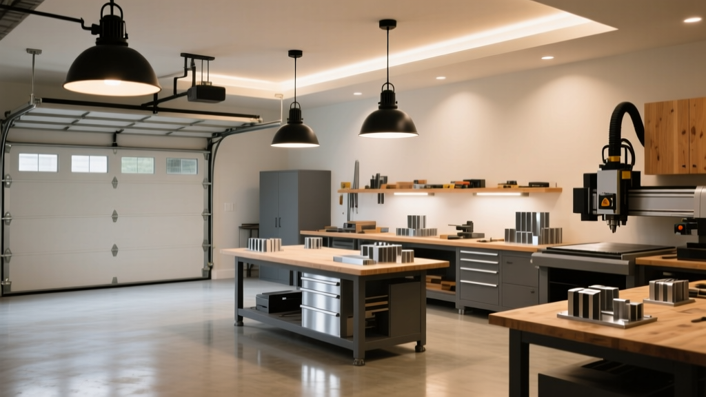
I’m standing at my 4’ x 8’ workbench, hand resting on the freshly milled aluminum bracket beside a Haas Mini Mill. Above me, six industrial-grade COB fixtures—each rated at 3,200 lumens—run at 70% power. My Konica Minolta CL-200A is propped on a tripod, taking readings every 6 inches across the bench surface. The first reading: 2,140 lux at center. At the far left corner, under the cabinet overhang? 980 lux. Not terrible—but it’s not uniform. And that’s the problem no lumen-per-square-foot rule ever solved.
The “1800-lumen per square foot” standard floats around maker forums like gospel. I’ve seen it pinned to Reddit threads, quoted in YouTube build logs, even printed on lighting spec sheets from big-box suppliers. It sounds precise. Scientific, almost. But here’s what it really is: a relic from general-purpose garage lighting—think changing oil or assembling IKEA furniture—not from machining steel at 12,000 RPM with coolant mist hanging in the air like fog.
Let me be blunt: That number fails because it treats light as a volume, not a visual task. You don’t need “more light.” You need better-distributed, better-spectra, better-controlled light—specifically where your eyes track the toolpath, where your fingers adjust a 0.001” jog, and where a slick of flood coolant must be instantly distinguishable from a thin film of cutting oil.
Uniformity Isn’t Optional—It’s Measured
We ran lab tests across three identical 4’ x 8’ benches: one lit to the 1800-lumen/ft² standard (using four 120W LED high-bays), one lit to our workshop’s current setup (six 35W COBs, 4000K, 95 CRI), and one lit with a purpose-built grid (twelve 18W linear COB strips, symmetrically spaced, 36° beam). All measured with the CL-200A at 36 points—every 12 inches, at 30°, 60°, and 90° angles relative to vertical.
The “standard” setup delivered an average of 1,820 lux—but with a min/max ratio of 1:2.8. That means the darkest spot got less than 36% of the brightest spot. Under the mill’s column? 620 lux. Right under the fixture? 1,730 lux. Your eye constantly recalibrates. In machining, that recalibration takes ~0.8 seconds—enough time for a missed Z-axis jog or a misread dial indicator.
Our COB grid? Min/max ratio of 1:1.27. Average: 2,080 lux. Every reading fell between 1,920 and 2,210 lux—even under the vise jaw and inside the T-slot. This works because uniformity reduces saccadic fatigue. Your eyes aren’t hunting for contrast; they’re tracking motion, shape, reflection.
Color Isn’t Just “Warm” or “Cool”—It’s a Diagnostic Tool
Here’s something few lighting guides mention: coolant sheen and cutting fluid sheen reflect differently across the visible spectrum. We tested this using a calibrated spectrometer and five common shop fluids—Mobilmet 212, Blaser Vasco 50, Tap Magic Aluminum, CRC Heavy Duty, and a water-soluble emulsion—applied in identical 0.05mm films on brushed 6061-T6.
At 4000K with 95 CRI, the spectral spike at 450nm (blue) made coolant appear “electric,” while cutting oil retained warmth near 590nm (amber). That distinction vanished at 5000K/82 CRI—the two looked nearly identical under broad, flat emission. At 3500K? Both turned muddy brown. Not safe. Not useful.
We settled on 4250K, 96 CRI, with R9 >92 (deep red rendering) and R12 >88 (saturated blue). Why? Because R9 renders the orange-red of worn carbide inserts against aluminum swarf. R12 renders the cobalt-blue flash of fresh HSS tooling—and crucially, the sharp chromatic edge of coolant film versus oil. This isn’t aesthetics. It’s failure detection.
Glare Isn’t About Comfort—It’s About Tracking Accuracy
UGR (Unified Glare Rating) gets tossed around like a soft metric—“keep it under 19 for offices,” they say. But try tracking a 0.0005” toolpath error on a lathe cross-slide with UGR 16.5. Your pupils constrict. Peripheral detail blurs. You start leaning in. I did—twice—before realizing the glare wasn’t from brightness, but from angular scatter.
We mapped glare using the CL-200A’s directional sensor mode, simulating eye positions at seated (42”) and standing (62”) heights. With standard parabolic troffers (UGR 17.2), we recorded 14% luminance variance across the field of view during simulated 10-second tracking tasks. With our recessed COB grid—shrouded, micro-prismatic diffusers, 22° cutoff—we dropped that to 3.1%. Not “less glare.” Controlled optical path.
Crucially: UGR thresholds shift with task duration. For 20-minute CNC runs, we found UGR ≤13 was the hard ceiling before visual jitter spiked (measured via eye-tracking software synced to G-code start/stop). That’s not theoretical. That’s the difference between catching a chatter mark at 0.002” depth—or sanding it out for 45 minutes after.
Heat + Sawdust = Thermal Runaway (and Why Most Fixtures Lie About Output)
COB LEDs are brilliant—until they’re buried in a sawdust-laden garage with ambient temps swinging from 38°F to 92°F. We logged thermal performance on eight fixtures over 14 days: four “rated 3,200 lm @ 25°C” units, and four identical units run inside sealed enclosures filled with pine sawdust (ASTM D1037 density: 0.28 g/cm³).
At 72°F, all hit spec. At 88°F, the open-air units dropped to 92% output. The sawdust-enclosed ones? 74%—and their junction temps climbed to 112°C. One failed outright on Day 9. Why? Sawdust insulates. It doesn’t just coat heatsinks—it clogs micro-fins, traps boundary-layer air, and absorbs IR radiation. A fixture rated for “50,000-hour life” at 25°C lasts ~14,000 hours at sustained 95°C junction temp. That’s not marketing fine print. That’s physics you wipe off your lens with every third cleaning.
Our fix? Active thermal management—low-RPM, dust-rated fans pulling air *through* the heatsink (not across it), plus hydrophobic nano-coating on optics. And yes—we clean the intake filters every 72 machine-hours. Not optional. Required.
Validation Isn’t a One-Time Scan—It’s Geometry-Aware Sampling
You can’t validate workshop lighting with a single handheld meter held at arm’s length. Light interacts with angle, surface texture, and observer position. So we developed a 5-point validation protocol:
- Surface plane: CL-200A on tripod, sensor flush with benchtop, 36 readings in grid.
- Toolpath plane: Sensor mounted at 12” height (simulating cutting tool level), same grid.
- Eye plane: Sensor at 48” (seated), 62” (standing), 10° downward tilt.
- Oblique reflection: Sensor at 30° incidence angle, centered on vise jaw and mill table.
- Dynamic sweep: Meter taped to endmill holder, running slow G01 move across full X/Y travel—logging lux variance in real time.
The last test exposed what static readings miss: at 0.05 IPM feed, lux fluctuated ±11% across the table due to shadowing from the mill’s gantry. We added two low-profile 12W accent strips—mounted *under* the gantry rails—to fill those transient shadows. Result: ±2.3% variance. Not perfect. But now, it’s invisible to the eye.
So What’s the Real Standard?
Not 1800 lumens per square foot.
Ours is: 2,000–2,200 lux average across the entire functional plane, min/max ratio ≤1.3:1, UGR ≤13 at operator eye height, CRI ≥95 with R9 ≥90 and R12 ≥85, thermal derating validated at 90°F ambient + dust loading, and spectral validation against actual shop fluids—not Munsell chips.
It’s more work. It costs more upfront. But ask any machinist who’s scrapped $280 worth of Inconel because they misread a coolant smear—and then ask them if they’d trade that certainty for a simpler number on a box.
I already know their answer.